to suit any application
Hospitals, universities, hotels, etc
Simple, clear
and user friendlyEfficient management of critical systems
Fire Alarm
Emergency Lighting
Allows Low-Skilled operation
PC based control
Improved record logging
Audit Trail
Multiple Users: 2000 max
Dongle protected
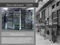
Introduction